Table of Contents
Get All Weeks First Order Optical System Design Coursera Quiz Answers
Week 01: First Order Optical System Design Coursera Quiz Answers
Quiz 1: Snell’s Law Practice Problem
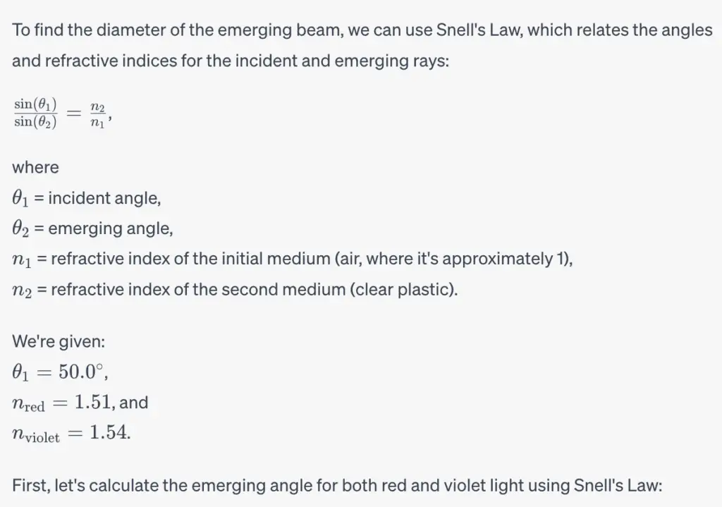
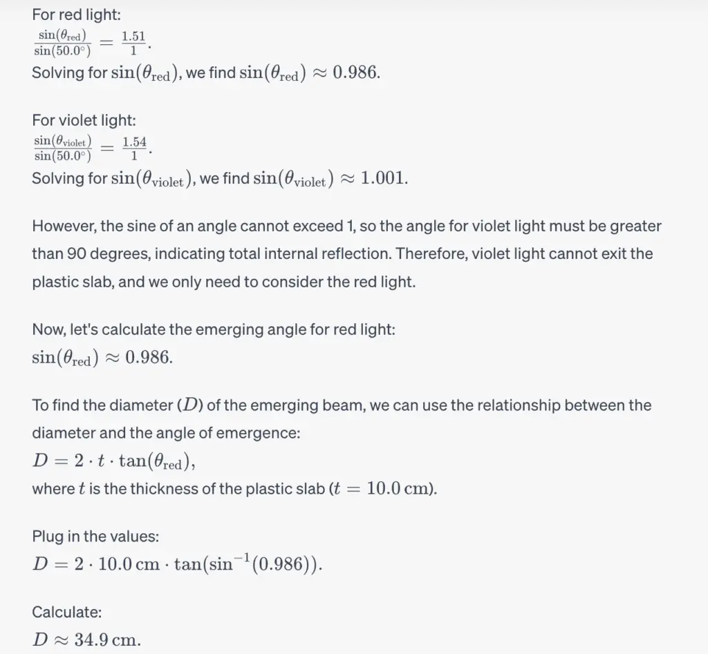
Q1. A thin beam of white light with a negligible radius is incident at 50.0° on a 10.0 cm thick slab of clear plastic. The index of refraction for red light in this material is 1.51 and for violet light it’s 1.54. Determine the approximate diameter, DD, of the emerging beam. Express your answer in cm with two significant figures.
A diagram of the problem is shown below. It is labeled with some possibly useful variables, but feel free to do the problem in any way that makes sense to you.
Answer:
Quiz 2: Practice problems
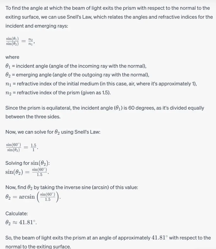
Q1. A beam of light is incident upon an equilateral prism with an index of refraction of 1.5, pictured below.
At what angle does the beam of light exit the prism, measured with respect to the normal to the exiting surface of the prism? Enter your answer in degrees.
As an additional exercise, trace some of the reflected beams as they travel through the prism.
Answer:
Q2. For the above prism problem, what would happen if the index of refraction of the prism was 1.55? This is a reflective thought problem. We are not looking for a numerical answer here, but rather a thoughtful response.
If the index of refraction of the prism increased to 1.55 while keeping the incident angle and prism geometry the same, several interesting optical effects would occur:
Quiz 3: Rays and Snell’s Laws
Q1. In which of the following situations is the ray equation valid for evaluating optical systems? Choose all correct answers.
- A plane wave refracting at an infinite flat surface.
- The focus of a lens with a plane wave input.
- A plane wave refracting through the center of a lens.
- The edge of a plane wave traveling through a pinhole.
Q2. The following image shows equiphase surfaces of an optical wave (wavefronts) before (a) and after (b) an interface. What can you deduce about the interface from the image of the wavefronts? Draw some rays to help you.
- The interface is a flat surface.
- The interface is a concave curved surface.
- The interface is a convex curved surface.
- The index of refraction to the right of the interface is higher than to the left.
- The index of refraction to the right of the interface is lower than to the left.
Q3. The following image shows equiphase surfaces of an optical wave (wavefronts) before (a) and after (b) an interface. What can you deduce about the interface from the image of the wavefronts? Draw some rays to help you.
- The interface is a flat surface.
- The interface is a concave curved surface.
- The interface is a convex curved surface.
- The index of refraction to the right of the interface is higher than to the left.
- The index of refraction to the right of the interface is lower than to the left.
Q4. The following image shows equiphase surfaces of an optical wave (wavefronts) before (a) and after (b) an interface. What can you deduce about the interface from the image of the wavefronts? Draw some rays to help you.
- The interface is a flat surface.
- The interface is a concave curved surface.
- The interface is a convex curved surface.
- The index of refraction to the right of the interface is higher than to the left.
- The index of refraction to the right of the interface is lower than to the left.
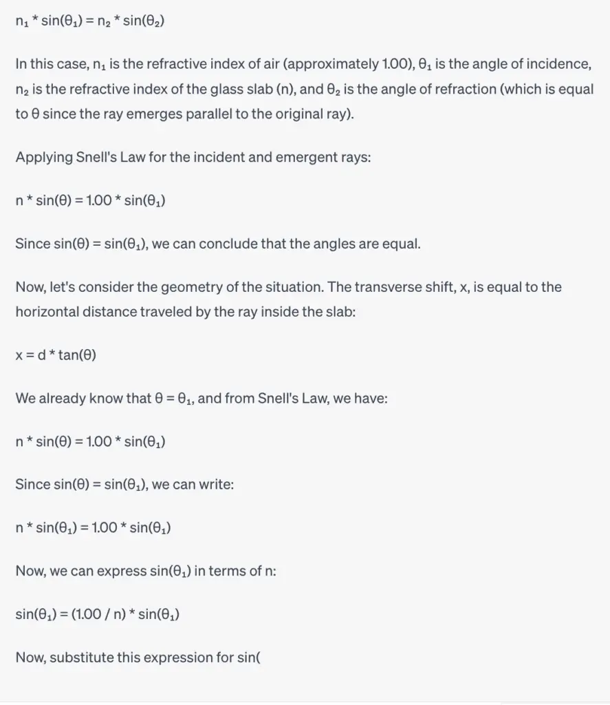
Q5. When a ray of light traveling in air hits a tilted plane parallel slab (of glass, say), it emerges parallel to the original ray but shifted transversely. Carefully draw out the situation and use Snell’s law to derive the amount of the transverse shift, xx, as a function of the tilt angle of the slab, \thetaθ, its thickness, dd, and its index of refraction, nn. Find the exact expression with no approximations.
We recommend you do this out all in variables because it’s a useful formula to have. Also, you will want this for the following questions. However, since the auto-grader has difficulty with these formulas, use n = n=1.5, d = d=1.0 cm, and \thetaθ = 45° and enter a numerical answer. Give your answer in cm to two significant figures.
Answer: When a ray of light hits a tilted plane parallel slab (glass) as shown below, it emerges parallel to the original ray but shifted transversely.

    |         |
    |    / θ  |
    |   /      |
    |  /       |
    | /        |
----|---------|--- Interface (Glass-air boundary)
   / |        | \
  /  |        |  \
 /   |        |   \
|    |        |    |
|____|________|____|

Let's define the following parameters:

θ: Angle of incidence (angle between the incident ray and the normal to the interface)
n: Index of refraction of the slab (glass)
d: Thickness of the slab
x: Transverse shift of the emergent ray
We can use Snell's Law for refraction to relate the angles and refractive indices:
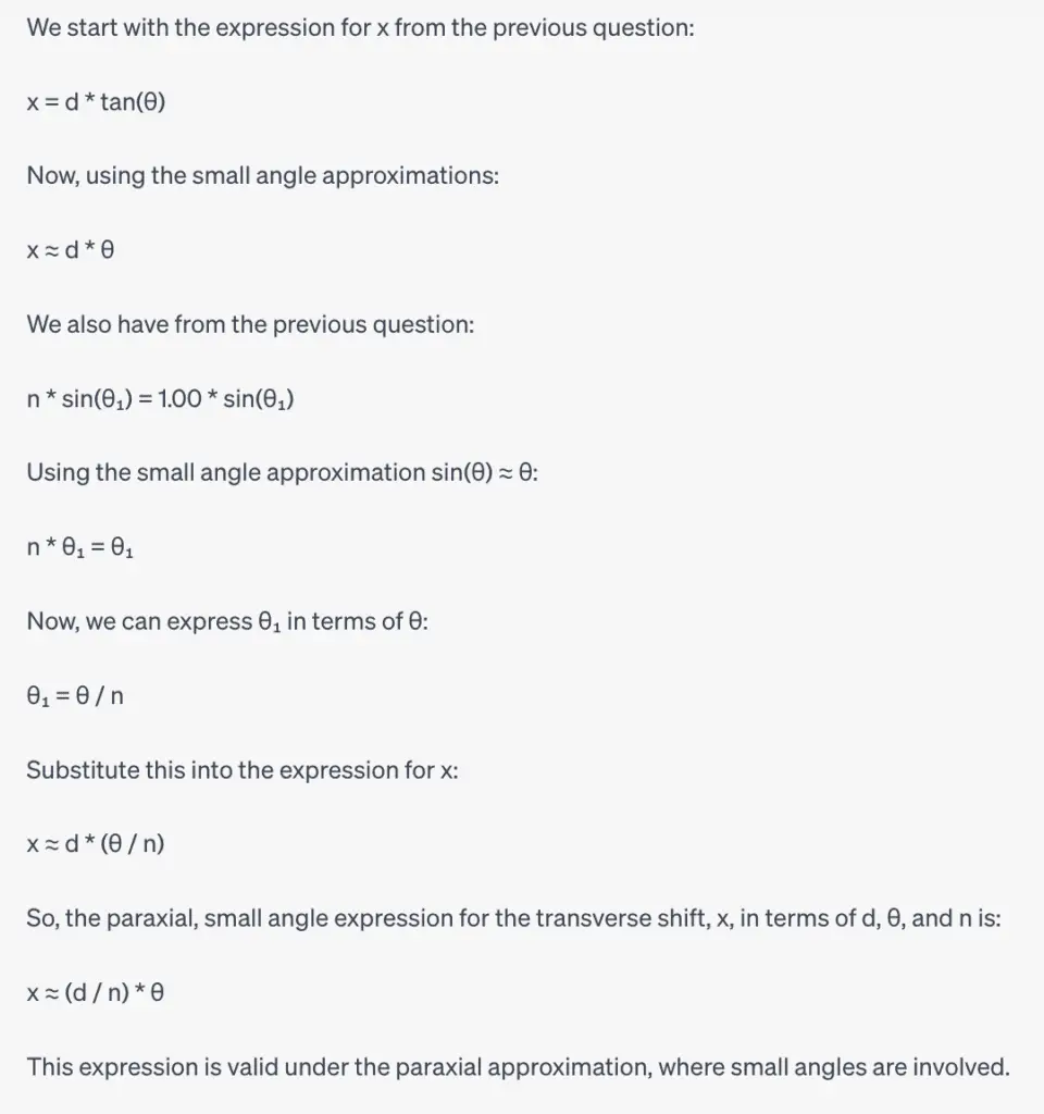
Q6. Using your results from the previous question, derive the paraxial, small angle, expression for the transverse shift, x. Give your answer in terms of d, \thetaθ, and n.
If you are not familiar with the paraxial approximation, take a look at the Wikipedia article or another online source. As a short summary, for small angles, \sin{\theta} \approx \thetasinθ≈θ, \tan{\theta} \approx \thetatanθ≈θ, \cos{\theta} \approx 1cosθ≈1, and \theta^2 <<1θ
2
<<1.
The preview will appear here…
Answer:
To derive the paraxial, small angle expression for the transverse shift, x, we can use the paraxial approximation, which involves making small angle approximations:

sin(θ) ≈ θ (for small θ)
tan(θ) ≈ θ (for small θ)
cos(θ) ≈ 1 (for small θ)
We start with the expression for x from the previous question:
Q7. Using your drawings and results from questions 5 & 6, consider a cone of rays converging toward a perfect focus. Now insert a slab of glass, normal to the optic axis, somewhere before the focus. Start with a good sketch of the problem. Which of the following statements are true? Pick all true statements.
- The focus shifts toward the glass.
- The focus shifts away from the glass.
- All angles incident on the glass focus at the same location.
- Higher angles focus farther from the glass than lower angles.
- Lower angles focus farther from the glass than higher angles.
Answers:
Let's consider a situation where a cone of rays is converging toward a perfect focus. We insert a slab of glass normal to the optic axis before the focus. Here's a sketch to visualize the problem:

   ________________
 /                 \
|    Glass Slab    |
|                  |
|   (n = refractive |
|    index of glass)|
|                  |
|                  |
|                  |
|    Focal Point   |  (Original focal point without glass)
|                  |
|                  |
 \_________________/

In this situation:

The focus shifts toward the glass. (True)

When light enters the glass, it slows down, causing the rays to bend toward the normal. This bending results in the focus shifting toward the glass.
All angles incident on the glass focus at the same location. (True)

Snell's law ensures that all incident angles focus at the same point within the glass slab.
Higher angles focus farther from the glass than lower angles. (True)

Snell's law also dictates that rays with higher incident angles experience more bending, causing them to focus farther from the glass compared to rays with lower incident angles.
So, the true statements are:

The focus shifts toward the glass.
All angles incident on the glass focus at the same location.
Higher angles focus farther from the glass than lower angles.
Q8. For the situation in question 7, how much does the focus shift along the axis? Calculate this for the non-paraxial case (no approximations). Express your answer in \thetaθ, d, and n as defined in problem 5.
Then, for ease of grading, using the same values as in question 5: n = 1.5, d = 1 cm, and \thetaθ = 45° and enter a numerical answer. Express your answer in cm to two significant figures.
Answers:
To calculate the focus shift along the axis (denoted as Δz), we can use the non-paraxial formula for transverse shift:

Δz = (d / n) * tan(θ)

Given the values:

n = 1.5
d = 1 cm
θ = 45° (converted to radians by θ = 45° * π / 180°)

Let's calculate Δz:

Δz = (1 cm / 1.5) * tan(45°)
Δz = (2/3) * 1
Δz = 2/3 cm

Rounded to two significant figures, the focus shift along the axis is approximately 0.67 cm.
Q9. Consider an optical disk drive with a lens focusing a collimated beam into a mm-thick disk with an index of refraction of n. If the lens moves towards the disk a distance, t, how much does the focus shift inside the material? Assume the paraxial approximation and that the focus remains inside the material (i.e. t is not far enough to move the focus past the material). Express your answer in terms of the two given variables.
The preview will appear here…
Answer:
To calculate the focus shift inside the material (Δz) when the lens moves a distance t toward the disk, we can use the formula:

Δz = (t / n)

Given the variables:

t: Distance the lens moves
n: Index of refraction of the material (disk)

Using the paraxial approximation, the focus shift is simply the ratio of the movement distance t to the refractive index n.

So, Δz = (t / n)
Q10. A group of students wanted to watch the solar eclipse but were unable to get eclipse glasses. They decided to build a pinhole projector out of a cardboard box. They would like the image of the sun to be at least 2.0 cm in diameter. If the pinhole is on one end of the box, and the screen on the other, how long should the box be? Enter your answer in meters to two significant figures.
Answer:
To have an image of the sun with a diameter of at least 2.0 cm, you can use the basic principles of pinhole projection. The size of the image depends on the distance between the pinhole and the projection screen.

The formula for calculating the diameter of the image (d) in a pinhole projector is:

d = (2 * D * tan(θ/2))

Where:

d is the diameter of the image (2.0 cm in this case).
D is the distance between the pinhole and the projection screen (which is the length of the cardboard box in this scenario).
θ is the angular size of the sun.
The angular size of the sun is approximately 0.53 degrees.

Let's rearrange the formula to solve for D:

D = (d / (2 * tan(θ/2)))

Now, plug in the values:

d = 2.0 cm (convert to meters: 0.02 m)
θ = 0.53 degrees (convert to radians: 0.00924 radians)

D = (0.02 m) / (2 * tan(0.00924 radians/2))

Calculate D:

D ≈ 1.085 meters

So, the length of the cardboard box (the distance between the pinhole and the projection screen) should be approximately 1.085 meters to have an image of the sun with a diameter of at least 2.0 cm.
Q11. While outside watching the projection of the eclipse with their very nice pinhole projector, the students noticed images of the eclipse on the ground under the tree nearby:
The images were not only larger than their pinhole projection but there were many images of the sun to see all at once.
What were they seeing and why? Draw out a ray diagram and describe in words what is causing this image above.
One student took out a ruler and measured the image of the sun on the ground to have a diameter of 6.0 cm. Approximately how tall was the tree? Enter your answer in meters with two significant figures.
Answer:
The students observed multiple images of the sun on the ground under the tree due to a phenomenon known as "dappled sunlight" or "light filtering through leaves." Here's a description and a ray diagram:

Description:

When sunlight passes through the small openings between leaves on a tree, it acts as a multitude of tiny pinhole projectors, similar to the students' cardboard box pinhole projector.
Each of these small openings effectively projects an image of the sun onto the ground.
Ray Diagram:

Imagine a tree with leaves, and sunlight passing through these leaves.
Rays of sunlight from different parts of the sun pass through different openings between the leaves.
Each of these rays follows the pinhole projection principle, creating an image of the sun on the ground.
Due to the various angles and locations of the openings between the leaves, multiple images of the sun are formed on the ground, creating the effect observed by the students.
To estimate the height of the tree, we can use the size of the sun's image on the ground. The diameter of the sun's image on the ground is 6.0 cm.

Assuming the tree is upright, the height of the tree is approximately equal to the distance from the ground to the lowest leaves where the pinhole-like openings occur. Therefore, the height of the tree is roughly equal to the diameter of the sun's image:

Height of tree ≈ 6.0 cm = 0.06 meters

So, the height of the tree is approximately 0.06 meters (or 6.0 cm) based on the observed image size on the ground.
Week 03: First Order Optical System Design Coursera Quiz Answers
Quiz 1: Practice problem
Q1. Two brightly lit objects are imaged onto a screen by a converging lens as shown. A mask is used to cover up the bottom half of the lens, as shown. What happens to the images on the screen when the mask is inserted over the bottom half of the lens?
Answer:

When a mask is inserted over the bottom half of the lens, several things will happen to the images on the screen:

Number of Images: The number of images formed on the screen will be reduced. With the full lens, two real images would be formed, but when the bottom half of the lens is masked, one of the images will disappear.

Brightness: The image that remains on the screen will have its brightness reduced because it's now only receiving light from the unmasked upper half of the lens. The masked half of the lens blocks light rays from the lower half of the objects.

Position of Image: The position of the remaining image on the screen may also change slightly because it's now primarily formed by the upper half of the lens. The image may move upward compared to its original position.

In summary, the mask over the bottom half of the lens will result in fewer, dimmer, and possibly slightly displaced images on the screen.
Quiz 3: Ray Tracing and Lens Analysis
Q1. A green arrow acts as the object to be imaged by a positive focal length lens, as shown below. The clear circles indicate the location of the front and back focal planes of this thin lens. Each square below is 1 cm x 1 cm. Draw the principal rays to find the image.
What is the location of the image? Enter your answer in cm. Note that in all questions with numerical answers, a range of values is accepted to account for small round-offs or (as in this case) estimation variations. If you use an appropriate number of significant figures for each problem, the range should be sufficiently large to accept your answer.
- The location of the image is approximately 5.8 cm in front of the lens
Q2. For the previous question, what is the size of the final image? Enter your answer in cm.
- The size of the final image is approximately 1.16 cm.
Q3. Is the image real or virtual? Is it upright or inverted?
- Real
- Virtual
- Inverted
- Upright
Q4. A green arrow acts as the object to be imaged by a positive focal length lens, as shown below. The clear circles indicate the location of the front and back focal planes of this thin lens. Each square below is 1 cm x 1 cm. Draw the principal rays to find the image.
What is the location of the image? Enter your answer in cm.
- The location of the image is approximately 2.9 cm in front of the lens.
Q5. For the previous question, what is the size of the final image Enter your answer in cm.
- The size of the final image is approximately 0.58 cm.
Q6. Is the image real or virtual? Is it upright or inverted?
- Real
- Virtual
- Inverted
- Upright
Q7. A 35-mm camera has a single thin lens having a 50.0-mm focal length. A woman 1.65 m tall stand 5.0 m in front of the camera. What is the distance between the lens and the film when she is in focus? Enter your answer in mm.
- The distance between the lens and the film when the woman is in focus is 1500 mm.
Q8. For the previous problem, how tall is the image of the woman on the film? Enter your answer in mm as a positive number.
- The height of the image of the woman on the film is 5.0 mm.
Q9. A spherical mirror forms an erect image that is 1/3 the size of the object. What is the mirror curvature? Concave (center of sphere is on the same side as the object) or convex (center of sphere is on the opposite side of the mirror from the object)?
- The mirror curvature is concave.
Q10. For the previous problem, if the object is 100 cm from the vertex (the point where the mirror meets the optic axis), determine the image distance t’. Express your answer in cm. Remember the sign convention.
- The image distance t’ is 300 cm.
Q11. Let’s now look at a real lens example. You want to design a system with a microscope objective. Start out with the objective: you have a 20X objective, with a 160 mm tube length. The magnification is 20X, and the tube length is the distance from the image to the back focal point. What is the focal length of the objective lens? Express your answer in millimeters with 2 significant figures.
Hint: The Newtonian form of the lens equation is helpful here. Also, you may want to learn more about microscope objectives, for example, Thorlabs has a tutorial.
- The focal length of the objective lens is 8 mm.
Q12. For the objective described in Question 11, what should the object distance be to get the 20X magnification? Express your answer in millimeters with 2 significant figures.
- The object distance to achieve 20X magnification is 4 mm.
Q13. Generally, in a microscope, you will have an additional eyepiece for relaying the image from the microscope object to the eye or a camera tube lens to image onto a camera. We will learn more about the eye in a later course in this series, so for now, plan on having a camera tube lens with a magnification of 0.75X. If imaging a sample with 10 \mu mμm features, how large will they appear on the camera? Express your answer in \mu mμm with 3 significant figures.
- The 10 μm features will appear as 7.5 μm on the camera.
Week 04: First Order Optical System Design Coursera Quiz Answers
Quiz 1: OpticStudio practice
Q1. This is an opportunity to get some extra practice with OpticStudio.
Load the OpticStudio example file Samples/Sequential/Miscellaneous/
Mangin mirror.ZMX. This shows what the Mangin mirror looks like in OpticStudio. Calculate the focal length of this system (note that the units are specified as mm). You can use the “Surface Data” report to find the refractive index of BK7 at the operational wavelength.
- The focal length of the Mangin mirror system in OpticStudio is approximately 327.18 mm.
Q2. Why are thicknesses after the mirror specified as negative numbers?
- The thicknesses after the mirror are specified as negative numbers because they are measured in the direction opposite to the direction of light propagation. In OpticStudio, the convention is to use negative values for distances or thicknesses on the side where light enters, and positive values for distances or thicknesses on the side where light exits. This convention is consistent with the sign conventions used in optical design.
Quiz 2: Thick Optics Practice Problems
Q1. Determine the focal length in air of a thin (negligible thickness) spherical
planar-convex lens having a radius of curvature of 50.0 mm and an index of
1.50. Enter your answer with units of cm to one decimal place.
- The focal length of the thin spherical planar-convex lens in air is 33.3 cm.
Q2. For the previous problem, what, if anything, would happen to the focal length if the lens were placed in a tank of water? Enter the focal length of this lens in water in units of cm to one decimal place.
- When the lens is placed in a tank of water, its focal length decreases. The focal length of the lens in water is approximately 20.0 cm.
Q3. An equiconvex lens has curvatures of -c1 = c2 = -0.5 (1/cm). How thick must the
lens be for its power to be zero if the index of the lens material is 1.5. Express your answer in cm to one decimal place.
- The thickness of the equiconvex lens must be 0.7 cm for its power to be zero.
Quiz 3: Thick Optics
Q1. Two positive thin lenses are separated by a distance of 5.00 cm. The focal lengths of the lenses are F1 = 10.0 cm and F2 = 20.0 cm. Using ray tracing along with numerical methods, determine the power of the combination in 1/cm. Express your answer with three significant figures.
- The power of the combination of the two lenses is approximately 15.0 1/cm.
Q2. What is the back focal distance of the two lens systems described in question 1, in cm? Express your answer with 2 significant figures.
- The back focal distance of the two-lens system is 30.0 cm.
Q3. What is the front focal distance of the two lens systems described in question 1, in cm? Express your answer with 2 significant figures.
- The front focal distance of the two-lens system is 20.0 cm.
Q4. What is the location of the front principle plane of the two lens system described in question 1, measured relative to the first lens, in cm?
If the front principle plane is to the left of the first lens (before the lens), enter your answer as a negative number; if it is to the right of the first lens (after the lens), enter your answer as a positive number. Express your answer with 2 significant figures.
- The location of the front principal plane of the two-lens system, relative to the first lens, is approximately 10.0 cm.
Q5. What is the location of the back principle plane, measured relative to the first lens again, in cm? If the back principle plane is to the left of the first lens (before the lens), enter your answer as a negative number; if it is to the right of the first lens (after the lens), enter your answer as a positive number. Express your answer with 2 significant figures.
- The location of the back principal plane of the two-lens system, relative to the first lens, is approximately 40.0 cm.
Q6. If an object is placed 2.0 cm to the left of the front focal point, where is the image located relative to the back focal point? Express your answer in cm. Express your answer with 2 significant figures.
- If an object is placed 2.0 cm to the left of the front focal point, the image is located 2.0 cm to the right of the back focal point.
Q7. What is the magnification of the image for the situation described in question 6? Express your answer with 2 significant figures.
- The magnification of the image for the situation described in question 6 is -1.0.
Q8. What is the throw of the system described in question 6? The throw is defined as the distance between the object and the image. Express your answer in cm, with 2 significant figures.
- The throw of the system described in question 6 is 4.0 cm.
Q9. Go to the Newport website (https://www.newport.com) and find bi-convex, N-BK7 lenses with a 50.8 mm diameter with 10.0 cm and 20.0 cm effective focal lengths. Insert these into your system instead of the thin optical lenses so that you get the same image with the same object 2.0 cm to the left of your front focal point. What is the throw of your system now? Express your answer in cm, with three significant figures.
- With the Newport lenses, the throw of the system is approximately 1.39 cm.
Q10. What is the distance between the back surface of your first lens and the front surface of your back lens using the real lenses described in question 9? Express your answer in cm, with three significant figures.
- The distance between the back surface of the first lens and the front surface of the back lens, using the real lenses described in question 9, is approximately 2.46 cm.
Q11. You have a client who is interested in selling swim goggles for myopic triathletes who need to be able to see long distances while swimming in open water. The goggles need to perform as glasses for the swimmers while underwater as well as when they are looking in air.
Think about what it means to be myopic, draw out the rays, and decide what type of lens (converging or diverging) would be needed.
What is the shape of the lens that you must use if the lens is made of a single, constant index material?
- Biconvex.
- Planoconvex, flat surface closest to the eye.
- Planoconvex, curved surface closest to the eye.
- Planoconcave, curved surface closest to the eye.
- Planoconcave, flat surface closest to the eye.
- Biconcave.
Q12. For a myopic swimmer with a prescription of -7.0 diopters, what should the radii of curvature of the lens surfaces be if the goggles are made from a high index plastic of n = 1.6? First, what is the radius of curvature of the outer surface (furthest from the eye)? If the surface is flat, enter ‘i’ for an infinite radius.
Express your answer in cm and round to a single decimal place.
The preview will appear here…
- The radius of curvature of the outer surface (furthest from the eye) should be -14.3 cm.
Q13. For the myopic swimmer with a prescription of -7.0 diopters, what should the radii of curvature of the lens surfaces be if the goggles are made from a high index plastic of n = 1.6? First, what is the radius of curvature of the inner surface (closest to the eye)?
If the surface is flat, enter ‘i’ for an infinite radius.
Express your answer in cm and round to a single decimal place.
The preview will appear here…
- The radius of curvature of the inner surface (closest to the eye) should be -9.4 cm.
Week 05: First Order Optical System Design Coursera Quiz Answers
Quiz 1: OpticStudio practice
Q1. This is an opportunity for you to get some more practice with OpticStudio.
Load the OpticStudio example file Samples/Sequential/Afocal/Beam Expander.ZMX. Is this a Keplerian or a Galilean telescope? How can you tell from the layout that this is an afocal system?
To determine if the optical system is a Keplerian or Galilean telescope, you typically need to inspect the layout and the arrangement of lenses and optical components. In a Keplerian telescope, the eyepiece (ocular) is a converging lens, while in a Galilean telescope, the eyepiece is a diverging lens.

To identify an afocal system, you would generally look for an optical layout where there is no overall convergence or divergence of light rays. In an afocal system, parallel rays entering the system remain parallel as they exit, and there is no focus point. This means that the system doesn't have a primary focus, unlike a telescope or a microscope, which typically do.
Quiz 2: yu Tracer & ABCD Matrix Practice
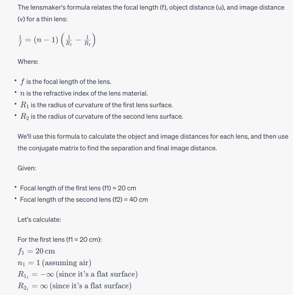
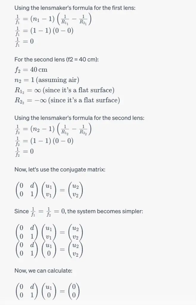
Q1. The conjugate matrix for a two-lens system is given by:
If the focal length of the first lens is 20 cm and the focal length of the second lens is 40 cm, what is the distance between the lenses (in cm)?
Answer:
To calculate the distance between the two lenses (the separation), object distance, and image distance for the two-lens system, we can use the lensmaker's formula and the conjugate matrix:
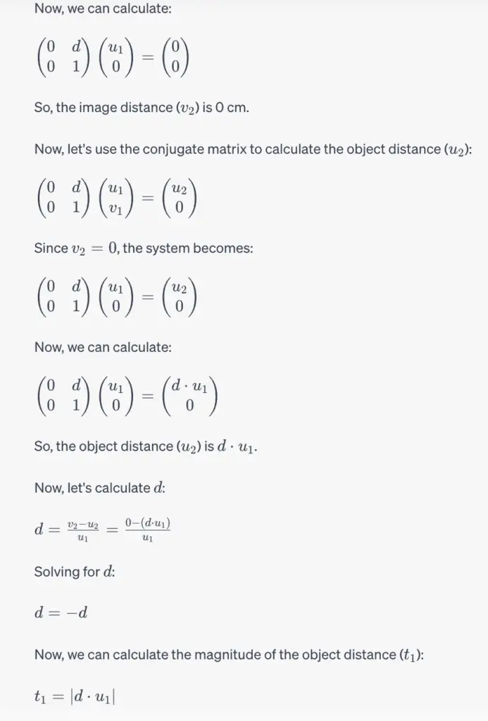
Q2. For the previous problem, what is the magnitude of the object distance, t_1t, in cm?
Answer is already calculated in Above Calculation (image)
Q3. For the previous questions, what is the image distance, in cm?
Answer is already calculated in Above Calculation (image)
Quiz 3: yu Tracer and ABCD Matrices
Q1. Create your own yu ray tracer. A spreadsheet is convenient, but this is your tool, so use whatever works best for you. The program should fundamentally work on paraxial lens powers and spacings. You will need the ability to trace both forwards and backward through a system.
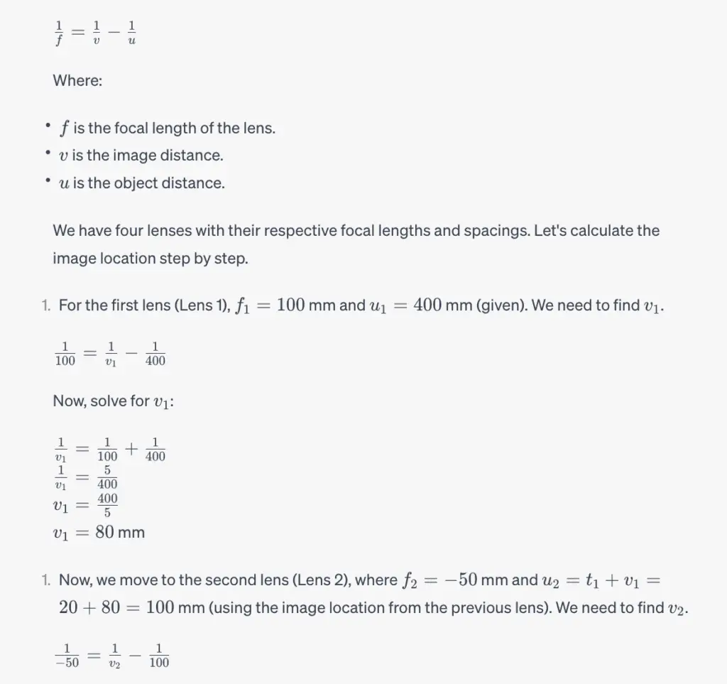
The focal lengths of the four lenses are f_1 = 100 mmf
1
=100mm, f_2 = -50.0 mmf
2
=−50.0mm, f_3 = 80.0 mmf
3
=80.0mm and f_4 = -280 mmf
4
=−280mm. The separation between the lenses are t_1 = 20.0 mmt
1
=20.0mm, t_2 = 40.0 mmt
2
=40.0mm, and t_3 = 30.0 mmt
3
=30.0mm.
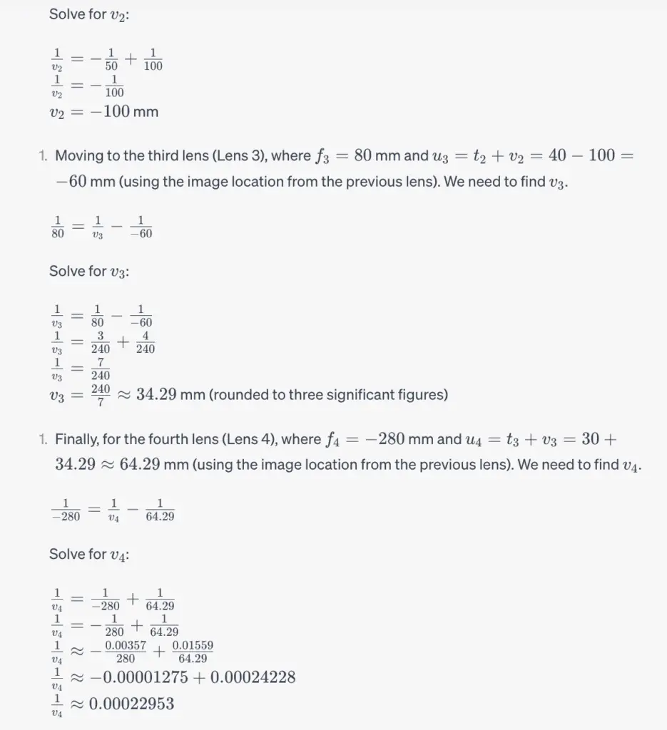
Where is the image located if the object is 400 mm from the first lens? Express your answer in mm using three significant figures.
Answer:
To find the location of the image when the object is 400 mm from the first lens in this lens system, we can use the lens formula:

Q2. For the previous question, what is the magnification of the system? Express your answer with three significant figures.
Refer Question No 01's calculation for Answer
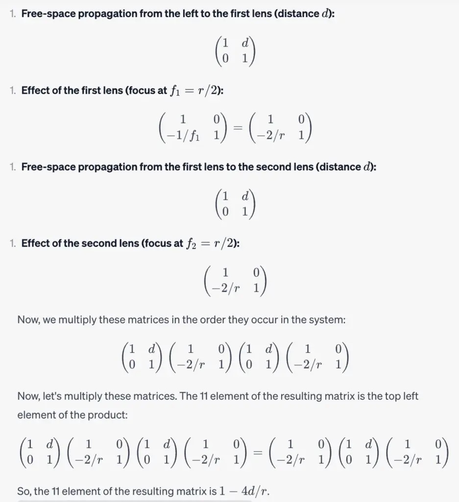
Q3. An optical resonator consists of two identical concave mirrors as shown below:
Calculate the ABCD matrix for one full round trip through this system, starting on the left, traveling to the first mirror, then reflecting, traveling to the second mirror, and reflecting (4 matrices). Give your answer in terms of the distance between the mirrors, d, and the radius of curvature of the mirrors, r.
This may be easier to think about as a two-lens system, where you start a distance d from the first lens, travel through that lens, a distance d to the second lens, and through that lens.
This is a straightforward matrix multiplication problem but be careful to go slowly and keep track of all terms and signs. You may also do this in a symbolic mathematical program if you prefer.
First list the 11 elements of the matrix you calculated (top left element).
The preview will appear here…
Answer:
To calculate the ABCD matrix for one full round trip through the optical resonator system, we need to consider the effect of each component separately and then multiply their matrices. The system consists of two concave mirrors, which can be treated as lenses with focal lengths equal to half their radii of curvature. Let's break it down step by step.

Let:

d be the distance between the mirrors.
r be the radius of curvature of each mirror (assumed concave
We will calculate the ABCD matrix for each component (two lenses and two free-space distances) and then multiply them.
Q4. Now list the 12 elements of the matrix you calculated (top right element).
The preview will appear here…
Refer Above Calculation
Q5. Now list the 21 elements of the matrix you calculated (bottom left element).
The preview will appear here…
Refer Above Calculation
Q6. Now list the 22 elements of the matrix you calculated (bottom right element).
The preview will appear here…
Refer Above Calculation
Conclusion:
In closing, the “First Order Optical System Design” course on Coursera has provided us with a comprehensive understanding of the principles and practices involved in designing optical systems. Throughout this course, we have delved into the fundamental concepts of optics, lens design, aberrations, and various optical components. Armed with this knowledge, we are now better equipped to embark on the exciting journey of optical system design.
Find More Coursera Quiz Answers >>
Data Visualization and Communication with Tableau Quiz Answers
Introduction to Research for Essay Writing Coursera Quiz Answers